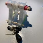
For this project I desinged a pulley and based my problem off one from the Systems of Masses worksheet we were given in class.
I am looking for the tensions of the ropes.
(images: left, orgiginal problem; right, the same problem but with my masses)
I ignored possible friction and other forces that may be playing on my pulley system.


First Models:
In the original models, the structures of the pulley are not ballanced, the circles are more ovals, there are buckets which would not have worked because the printed model was not tall enough for such features.
Final components, to be printed:
Some features that were adjuset with the final designes are seen with the pulley suport (right) the structure has a much larger open space in the center (done to remove waste and printing time), the top part of the pulley suport is a circle insead of an oval, and lastly there are two holes of the bottom of the suport that will alow for dowels to go through, joinging both suports to create a more ballanced system.
The sizing was also changed, the holes where the dowel goes through were changed to be the same size and the overall size of the entire peice was made to be smaller.
All put together:
I put elastics on the sides of the dowels to prevent the peices from sliding apart or moving, the elastics also ensured that it could be taken apart or adjusted if things were not working.
as you can see in the videos above I was having issues with how the pulley was sliding (summary: it wasn’t), by putting the rope and the weights on the inside of the lower suport dowles the whole pulley was able to work better. (see video bellow)
The pulley needs to be heald above a surface in order for it to function because the stucture is too small compared to the size of the weights.
Math:
| Masses |
|
| 1st mass (single mass) | 0.0114kg |
| 2nd mass (middle mass) | 0.00643kg |
| 3rd mass | 0.0134 |
Fstart=(0.00643 + 0.0134)(9.8)=0.194
Fstop=(0.0114)(9.8)=0.112
ΣF=Fstart+Fstop=(0.194+0.112)=0.306

=9.81m/s^2
T1=T1+Fg=ma
T1=T1+(0.0114)(9.80)=(0.0114)(9.81)
T1= 0.117+0.112
T1=0.229N
T2=T2+Fg=ma
T2=T2+(0.0134)(9.80)=(0.0134)(9.81)
T2=(0.131)+(0.131)
T2=0.262N
Another example:


In this example I used less weight and a shorter string so that the pulley sysrtem is self suficient and does not need to be heald up.
Math:
Fstart=(0.00740)(-9.80)= -o.o725N
Fstop=(0.00348)(9.80)=0.0341N
ΣF-Fstart+Fstop=(-0.0725)+(0.0341)=-0.0384N

=-0.398m/s^2
T1+Fg=ma
T1+((0.00740)(9.8)=(0.00740)(-0.398)
T1=0.0725+(-0.00295)
T1=0.0696N
Conclusion: My pulley works. I can see from the different sets of weights that the tension changes when the weights change, the larger weight system had a tension of 0.229N and my smaller weight system had a tension of 0.0696N. The different lengths of the ropes, the data is not consistant. What I do know is that weight and the length of the rope/string can affect the tension of the rope/string.
 Loading...


