The drive train serves two functions:
It transmits power from the engine to the drive wheels
It varies the amount of torque (torque vs. speed)
Power – is the rate or speed at which work is performed.
| Torque – is turning or twisting force, like what our crankshaft, driveshaft, axles, wheels and tires are doing.
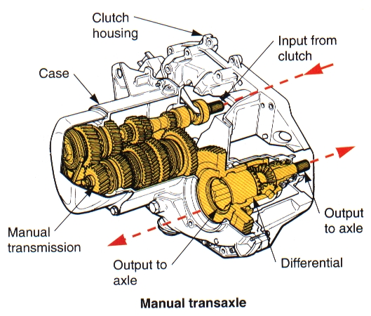
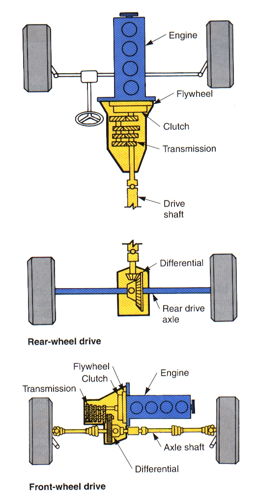
“Horsepower sells, but Torque wins races” Drivetrain configurations vary, depending on the design of the vehicle. The drivetrain parts commonly found on a Front-engine, Rear-wheel-drive vehicle (FR) include: Clutch Transmission Driveshaft Rear axle assembly The drivetrain parts used on most Front-engine, Front-wheel-drive vehicle (FF) include: Clutch Transaxle Drive axles Front Wheel Drive (FWD) has the advantage of weight over the drive wheels (awesome in winter), and cheaper to produce (less parts, less structural rigidity required in the chassis). Rear Wheel Drive (RWD) tends to be better balanced in handling. |
CLUTCH |
| A clutch is used to connect and disconnect the engine and manual transmission or transaxle. The clutch is located between the engine and transmission.Only vehicles with manual transmissions require a clutch. Vehicles with automatic transmissions use a fluid coupling, or torque converter, which automatically disengages the engine and transmission at low engine speeds.
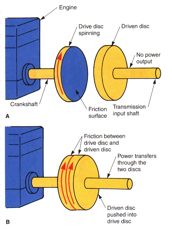
Power flow from one unit to another can be controlled with a DRIVE disc and a DRIVEN disc. When the two friction surfaces of each disc are pushed together, power is applied from the engine to the transmission. In an automotive application, the Drive has two friction surfaces (the flywheel and the pressure plate) that grip both sides of the Driven (clutch disc). The Pressure Plate clamps the Clutch Disc against the Flywheel. |
Clutch Components: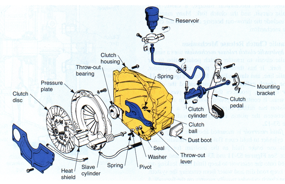
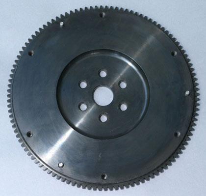
FlywheelAttached to and rotates with the engine. Usually equipped with a smooth machined surface for the clutch disc’s contact. Flywheels can be made out of Cast Iron, Forged Steel, or Aluminum (with a steel insert for the clutch). The flywheel also includes a Ring Gear to enable the starter to crank the engine over.
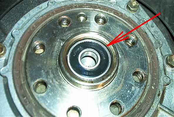
Pilot BearingPressed into the end of the crankshaft or the flywheel, it supports the input shaft of the transmission. The bearing might be make of bronze and require greasing, or sealed ball bearing that cannot be serviced. Some vehicles with short input shafts have no pilot bearing at all.
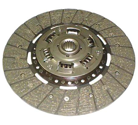
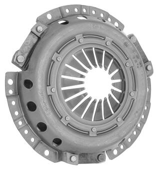
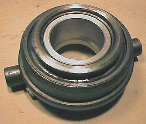
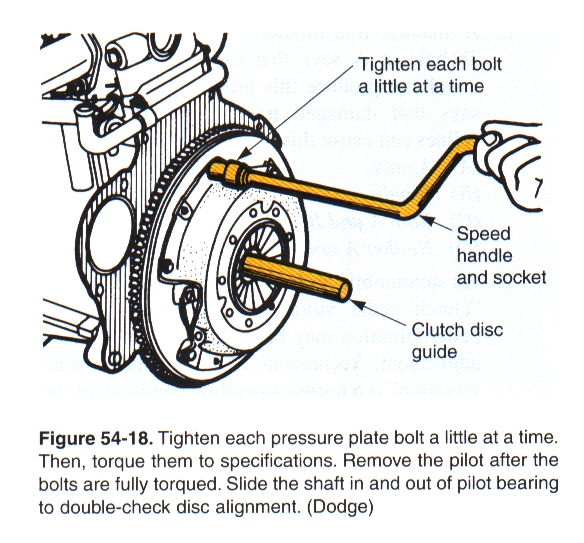
Clutch DiscSplined onto the input shaft of the transmission. The clutch has a soft, consumable friction surface on both sides. It must slip enough to make its application gradual, yet grip enough to stay connected, plus operate quietly. It also has torsion springs built in to absorb the shock of application. The size and location of the torsion springs mean that the disc can only be installed ONE way. When abused, the heat from friction usually glazes the clutch disc, which makes it slip, which turns the flywheel and pressure plate blue, requiring machining and/or replacement. Pressure PlateA spring-loaded device that can either lock or unlock the clutch disc and the flywheel. It bolts to the flywheel, and the clutch disc fits between. The pressure plate will apply the clutch disc to the flywheel with a cast iron friction surface through either coil springs (Borg & Beck) or a diaphragm spring. Throw-Out BearingAlso called Release Bearing. A sealed ball bearing unit that goes between the clutch lever and the pressure plate. This allows us to apply the clutch with little to no wear on either the clutch fork or the pressure plate. When they wear out, they tend to squeal when the clutch is applied.
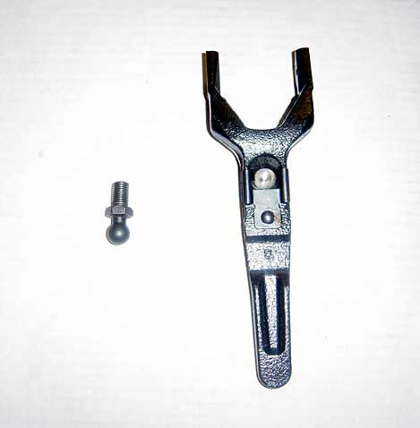
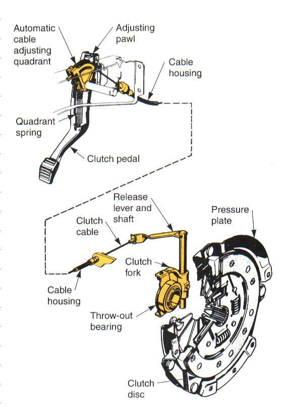
Clutch ForkTransfers motion from the clutch release mechanism to the throw-out bearing and pressure plate. These are a simple lever that can be controlled by a cable, a hydraulic slave cylinder, or a mechanical linkage to the clutch pedal assembly. Its pivot should be well lubricated.
Clutch Linkage MechanismThis is the pedal assembly under the dashboard. The pedal freeplay is often adjustable, and should be set so there is no more than one inch of free-play before the clutch begins to be applied. As the clutch friction surfaces wear, this free-play decreases, and will require re-adjustment.
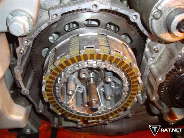
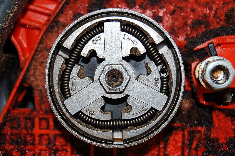
Cars and trucks use a single disc clutch mounted “dry.” Motorcycles mount their clutches inside the transmission case, immersed in the transmission oil. Because they are small in diameter, they usually make up the surface contact area with multiple clutch discs (called “multi-disc”). Both go-karts and chain-saws use a centrifugal drum clutch, where rotating weights inside a drum are flung outward as engine speed increases. When the weights contact the drum, the drum begins to turn with the weights and crankshaft. This allows the engine to idle without driving anything, and then drive once the engine speed is increased.
|
|
TRANSMISSION |
|
Manual TransmissionAn engine develops maximum power over a narrow range, but our vehicle needs to operate over a wide range of speeds. In order for a “narrow band” engine to move a vehicle through a “wide band” of operation, we need some method of “gearing down” the engine speed to something usable. The car’s drivetrain uses physical gears to accomplish this, and through an extra gear to change direction, adds a method to “back up” the car. A manual transmission should be able to: Be able to increase torque going to the drive wheels for quick acceleration Supply different gear ratios to match different engine load conditions Have a reverse gear for moving backwards Provide the driver with an easy means of shifting transmission gears Operate quietly, with minimum power loss |
GEAR RATIOS |
GearsAre round wheels with teeth machined around the perimeter. By meshing the teeth, one gear can turn another. The “Gear Ratio” is merely the ratio between the Driven Gear, and the Drive Gear. If a 3″ gear is DRIVEN by a 1″ DRIVE gear, the math is 3/1, or 3:1. Driven/Drive. You did this is Math. I know, because I taught it. Mantra: “Driven over Drive, Driven over Drive, Driven over Drive, Driven over Drive, Driven over Drive, Driven over Drive, Driven over Drive, Driven over Drive, Driven over Drive, Driven over Drive, Driven over Drive, Driven over Drive, Driven over Drive, Driven over Drive, Driven over Drive.” Say it with me….
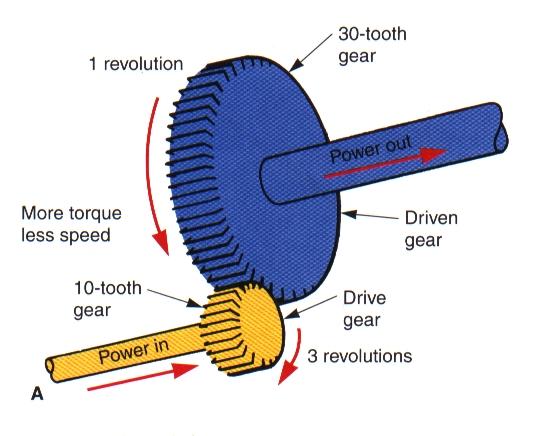
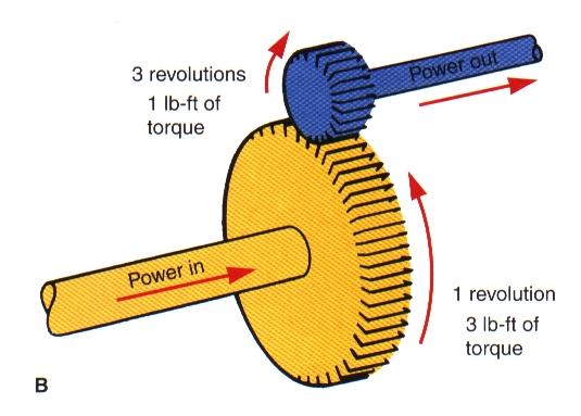
Gear RatiosThe number of revolutions a DRIVE gear must turn before the DRIVEN gear completes one revolution. They are calculated by dividing the number of teeth on the DRIVEN gear by the number of teeth on the DRIVE gear. Look at example A: Drive gear = 10 teeth Driven gear = 30 teeth The 10-tooth drive gear has to turn three times in order to turn the 30-tooth driven gear once. (Driven) ÷ (Drive) = (Ratio) (30) ÷ (10) = 3/1 This is a 3:1 ratio This is underdriven, and increases torque at the expense of speed. Now look at example B: Drive gear = 30 teeth Driven gear = 10 teeth If the 30-tooth drive gear is turned once, the 10-tooth driven gear will turn three times. (Driven) ÷ (Drive) = (Ratio) (10) ÷ (30) = 1/3 This is a 1:3 ratio This is overdriven, and increases speed at the expense of torque.
All gear ratios are found using the same method: (Driven) ÷ (Drive) = (Ratio)
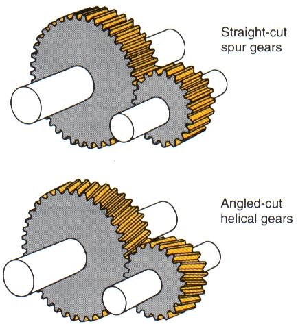
For example, an 11 tooth gear driving a 32 tooth driven gear, would have a gear ratio of 2.91:1 (32/11=2.91). Transmission gear ratios vary from one manufacturer to another. The gear ratios are chosen to best suit the power characteristics of the engine, the weight and the purpose of the vehicle. Generally, approximate gear ratios are 3:1 for first, 2:1 for second, 1:1 for third or high gear, and 3:1 for reverse. When a pair of gears are driving another pair of gears, their ratios must be multiplied to find the final gear ratio (this will be needed when we look at how a manual transmission works). Gear Reduction and OverdriveGear Reduction – occurs when a small gear drives a larger gear to increase turning force, or torque. 4.30:1 is a lower gear than 3.10:1 (the output will be a lower speed). Overdrive – occurs when a large gear drives a small gear to increase turning speed, at the cost of torque Gear TypesSpur Gears – also called straight-cut gears. Very strong, and very noisy. Still used as the reverse gear (notice the “gear whine?”). Helical Gears – Have their teeth cut machined at an angle. Quieter than spur gears. LubricationThe transmission gears rotate in a bath of oil inside the transmission case. Typically 80W90 gear oil is recommended for most transmissions, but check your manufacturer’s recommendations. Too little oil, and the bearings and gear may run dry and be damaged. Too much oil, and the transmission may leak, or the oil might be whipped into bubbles which don’t lubricate well. The wrong oil, and bearings, gears and syncros might be damaged. Some transmissions use engine oil, and others use automatic transmission fluid. Check the Manual – guessing is bad!! |
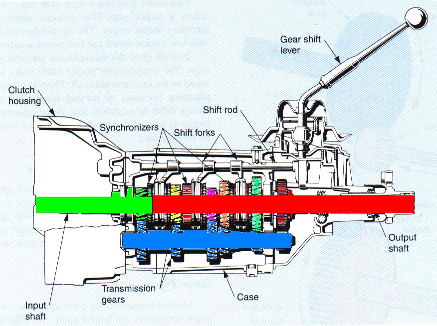
ShaftsThe transmission has four shafts:
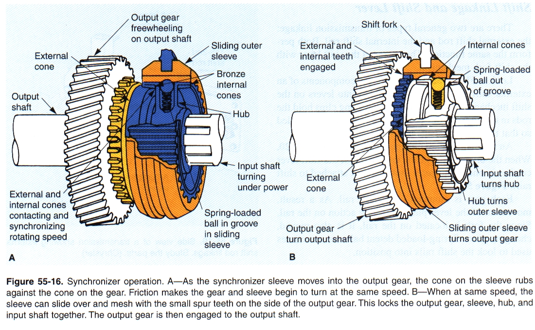
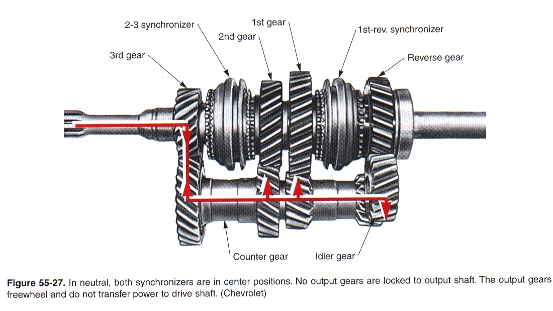
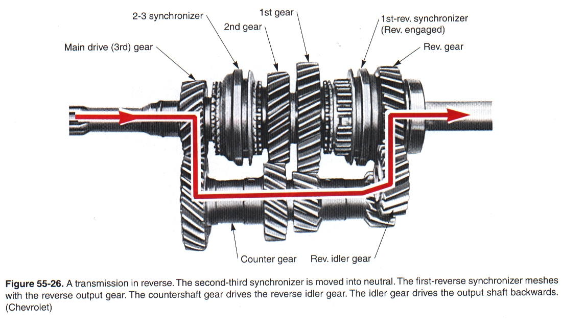
Input Shaft – Driven by the engine through the clutch. The input gear is one-piece with this shaft, and is in constant mesh with the Countershaft. Countershaft – also called the Cluster Gear Shaft. It is usually located below the input and output shafts. The Cluster Gear rotates on this shaft, turning the gears on the output shaft. All the gears are in constant mesh, and the cluster gears are all “fixed” together. Output Shaft – provides power to the driveshaft by locking the rotation of a particular gear to the shaft through the synchronizer assembly. ALL the gears slip on this shaft unless they are SELECTED and LOCKED to the output shaft by the Synchronizers (see below). Reverse Idler Shaft – (not visible in this picture) Holds an idler gear that can be inserted between the cluster gear and output shaft to change rotation SynchronizersA brass toothed ring used to match gear and shaft rotation speeds to make shifting smooth and effortless Internal and External tapered cones act as a friction brake Teeth engage splines on the Synchronizer Sleeve Locks the selected output gear TO the output shaft LEFT: gear is freewheeling (not selected) RIGHT: gear locked to shaft via Synchro Sleeve
Let’s look at a simple three-speed manual transmission: Neutral
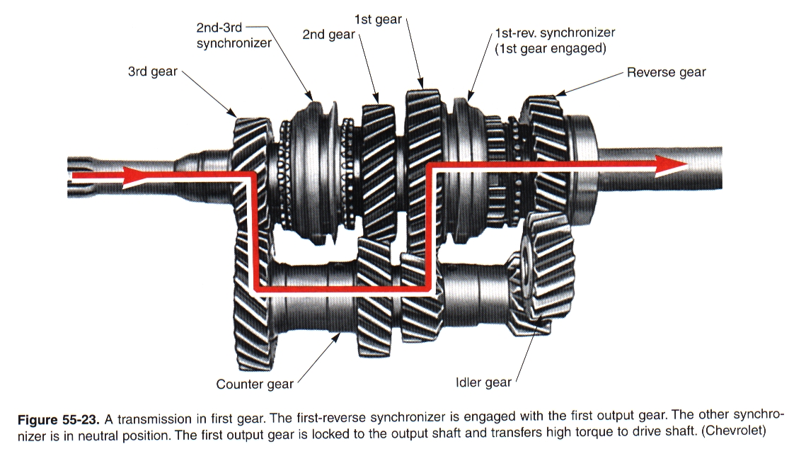
1st Gear
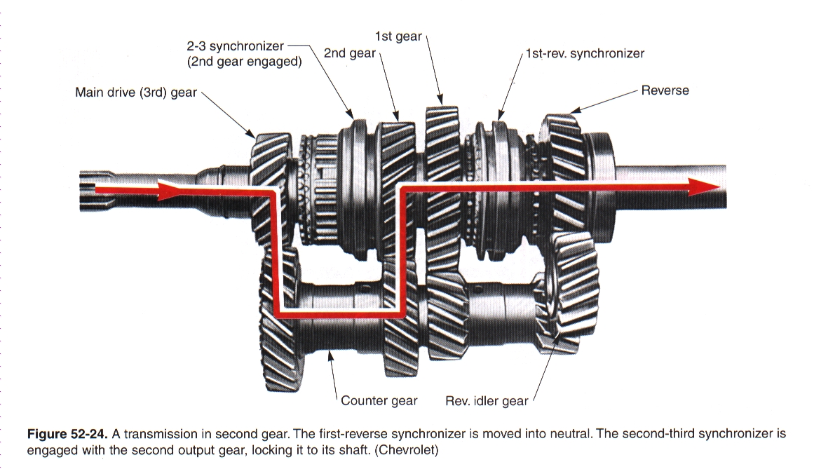
2nd Gear
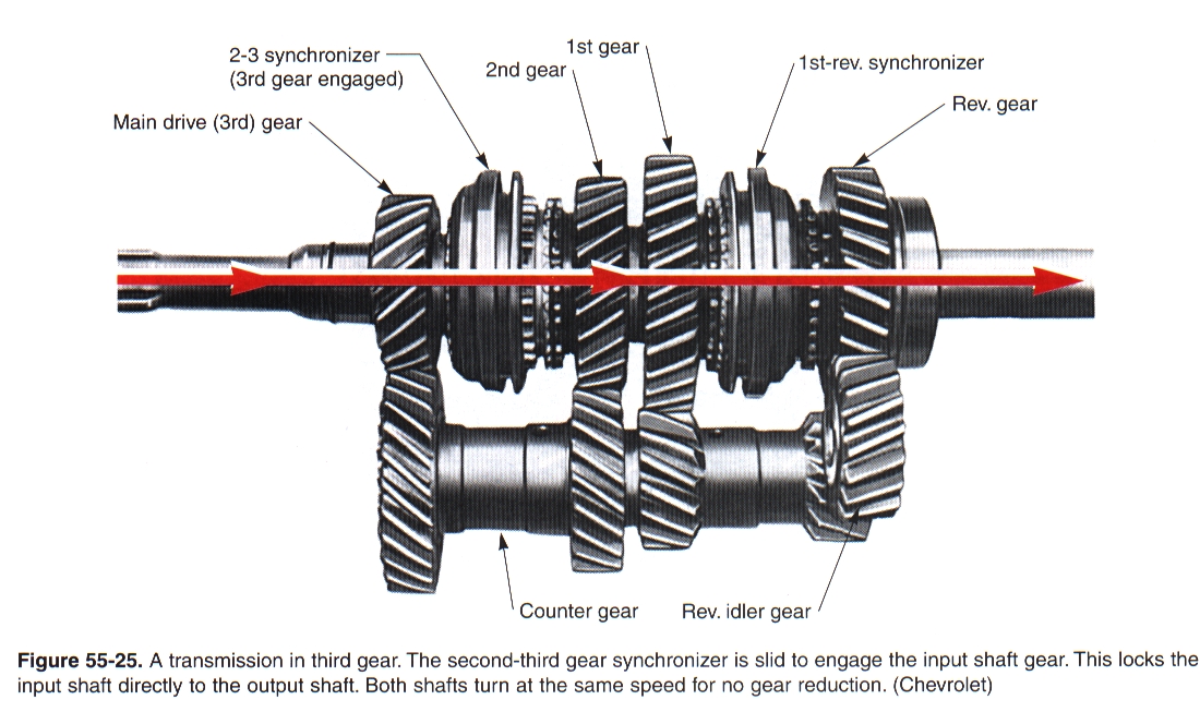
3rd Gear
Reverse Gear
|
DRIVESHAFT |
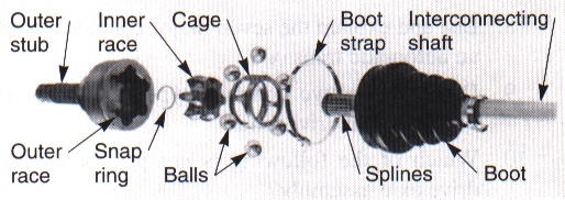
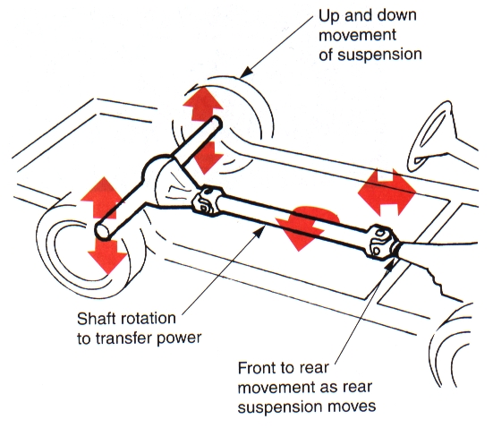
PurposeThe driveshaft transfers the drive from the transmission to the rear axle. It must allow a smooth transfer of power yet allow the suspension to move up and down. Because the axle moves up and down and the transmission doesn’t, a slip yoke is required to allow any change in drive shaft “length.”
|
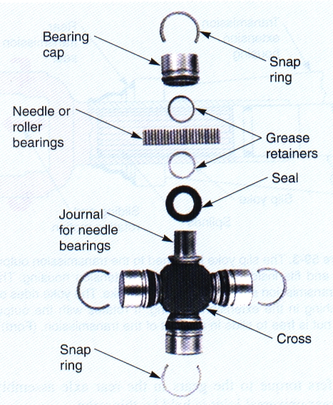
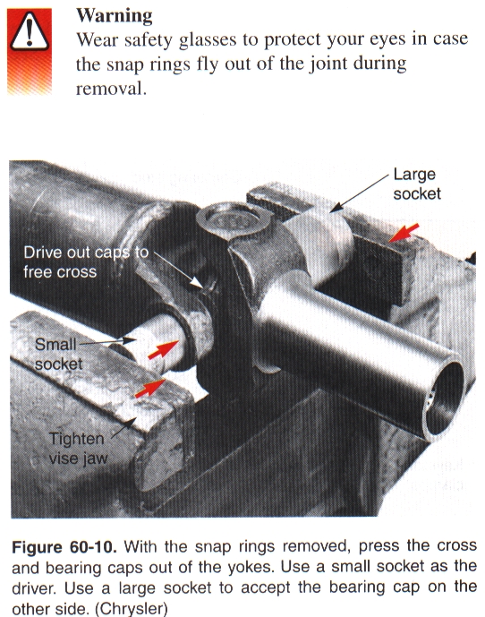
Universal JointsA “flexible” joint that allows the rotation and vertical movement The most common type used a Cross-and-Roller Universal Joint. It consists of four bearing caps, four needle bearings, a cross, grease seals, grease retainers and snap rings. Snap rings hold the bearing caps stationary in the driveshaft yokes. The cross is free to rotate inside the caps and yokes. While some universal joints can be greased as part of their maintenance, most are not. When they wear out, they usually produce a “clunk” sound as the drivetrain is loaded and unloaded. They may also squeak due to lack of lubrication. When abused, they can fail. A broken rear U-Joint will usually slap around the back of the car floor. A broken front U-Joint could drop the driveshaft onto the ground and possibly pole-vault the car if it encounters something solid. While greasable U-Joints are great for maintenance, the holes drilled through them for greasing makes them weaker. I once had a little Ford Pinto that had the 2.0L engine removed and a 5.0L engine installed. It still used the original (very weak) rear axle. With a set of really wide tires, the pinion flange on the axle would usually shear off and the flailing driveshaft would try to pummel its way up through the floor. There was a lot of shrapnel damage under that car. Mr. Wellwood’s Motto: “If you don’t break traction, you’re gonna break something else!” When replacing U-Joints, always use a press or a large vise to press out the bearing caps. Never use a hammer. Beating on the driveshaft with a hammer can damage the driveshaft, producing vibration or preventing the new joint from seating correctly.
|
|||
REAR AXLE ASSEMBLY |
|||
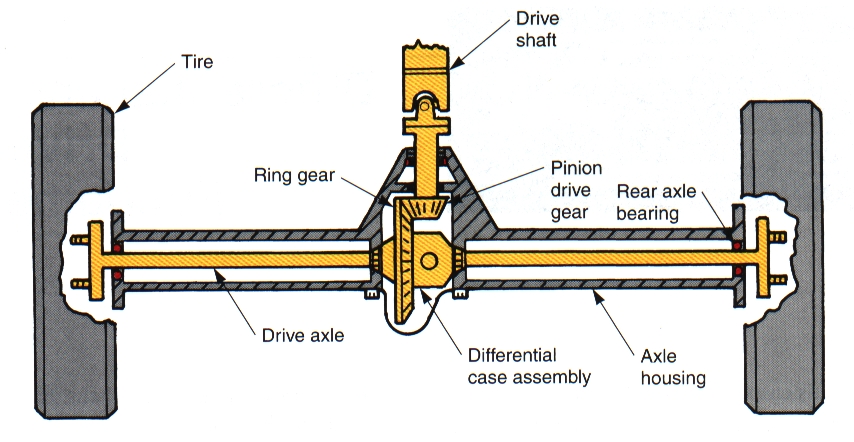
ComponentsIn a conventional rear wheel drive, a beam axle assembly encloses the final drive gears, differential and axle shafts in one housing. A ring gear and pinion gear transfers the drive through ninety degrees, and provides a final gear reduction to the driving road wheels. Hypoid bevel gears are normally used for this purpose. They are quiet, allow a lower the driveshaft height, and are quite strong. With the carrier bolted to the axle housing, the splines on the axle shafts can engage with the splines of the differential side gears, and drive is transferred through the differential case and gears, to the road wheels.
DifferentialIf the vehicle had both rear wheels solidly connected together, much like a go-kart, the vehicle would be a nightmare to steer. When a car turns, the inside wheels must turn a smaller circle than the outside wheels. A differential allows there to be a difference in speed between the wheels, yet still apply power to the drive wheels. This video (Around The Corner) is absolutely awesome at explaining how a differential works. This video is the absolute best I have ever seen:
|